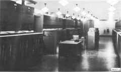


The 82B1 system was an automatic switching system with incoming and outgoing teletype lines. Cross-office traffic was at 200 wpm.
See Bell Laboratories Record, May 1960, August 1960, February 1961, April 1961, and October 1961.
82B1 system at Cheltenham 1959 |
82B1 system at Trenton 1950s |
Trenton - 1972 |
The first Navy 82B1 was opened in 1958 at Trenton NJ. Subsequent centers were
opened at Cheltenham, San Diego, Stockton, and Norfolk.
The Trenton system
diagram is below - Here are the PDF versions for all 5 system diagrams...
3.4.2 Automatic Relay Center (82-B-1).
The 82-B-1 is a fully automatic message-switching center (Figure G-5). Single- and multiple-address messages in the 5-unit International Number 2 Teleprinter Code in ACP 127 format are handled. This center consists primarily of self-contained ILU's and OLU's, which function as a complete switching center with no supplementary
cross-office equipments. Each incoming or outgoing line can be arranged to operate at 60, 75, or 100 wpm.
The ILU director is the key element in this switching center. It reads, analyzes, and stores all routing indicators, and selects the proper outgoing line for each addressee. When the outgoing line is identified, the director sends a request to transmit to the selected unit.
Cross-office transmission does not start until the outgoing line typing reperforator is free. A message being sent to one or more outgoing lines automatically brings about routing line segregation. An error in the heading sends the message to the intercept position for correction, after which it is reintroduced into the system. A preemptive message is given preferential treatment, but no outgoing messages are canceled in its favor.
Each ILU contains three
reperforator-transmitters, two for incoming lines, the other for the director circuit. These units copy the message and send the information cross office to the OLU. The director circuit reads and stores the routing indicators and precedence and indicates that the cross-office path is established wherein the message is automatically transmitted to the OLU and the director disconnects. If the request to transmit is denied, the ILU waits until the outgoing line is free. Storage for 12,000 characters is provided at each ILU.
When the ILU director detects a multiple-address message, it translates all the routing indicators, etc., but does not transmit until all the outgoing lines are available. A monitor records a tape copy of each outgoing message.
Each OLU serves four outgoing lines with associated reperforator-transmitter units controlled by two bid receiver circuits. Each OLU also contains two crossbar switches, which perform all cross-office connections. Each outgoing crossbar switch is capable of connecting to any ILU.
Incoming messages with heading errors are automatically sent to the intercept position where they are corrected and then reinserted into the system through a local send station.