AN/FRR-60 Diversity Receiving System
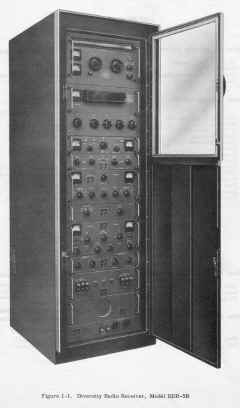
Usually in dual-diversity configuration - coupled with AN/FGC-60 FSK
converter system, this makes up AN/FRR-73.
My restoration of an AN/FRR-60 system.
| Manufactured by TMC - See K4OZY's DDR-5
web page |
| AN/FRR-60(V) |
TMC DDR-5(V) |
| AN/FRR-60(V)1 |
TMC DDR-5A-5D/5D |
| AN/FRR-60(V)2 |
TMC DDR-5A |
| AN/FRR-60(V)3 |
TMC DDR-5B |
| AN/FRR-60(V)4 |
TMC DDR-5B3 |
| AN/FRR-72 |
TMC DDR-5C/MSGA-1/ARCA-1 |
| AN/FRR-73 |
TMC DDR-5A/MSGA-1 |
| AN/FRR-74 |
TMC DDR-5K |
Frequency synthesized in 100 cps steps from 2-32 mc . Each receiver section has 2
independent outputs.
One version has "Technimatic" remote control.
- Synthesizer provides 1 part in 10^8 per day stability over 15 degrees C
- Synthesizer operates from 1mc master oscillator
- MC selector switch selects (using crystal filters) 1 of 31 harmonics of 1mc master oscillator
as HF mixer signal
- Master oscillator is divided down by phantastron decade dividers to
100kc, 10kc, 1kc, 100cps reference signals
- Reference signals go to blocking oscillators producing rich harmonics
- Appropriate harmonics are selected by 4 decade switches each selecting 1
of 10 crystal filters
- All selected harmonics are mixed together to create 4.25 to 3.25 mc
synthesized frequency (in 100cps steps)
- Tuner supplies 3.75-33.75 mc HF oscillator (HFO) signal to Synthesizer.
- Synthesizer mixes selected harmonic of 1mc master oscillator with
Tuner HFO to yield 4.25-3.25 mc
- Phase comparator compares Tuner's 4.25-3.25 mc signal with Synthesizer's 4.25-3.25 mc
signal
- DC correction voltage is fed back to varicaps in Tuner's HFO to lock
it to Synthesizer - Voila!
- Some systems have 2 synthesizers, one for each receiver
- Other systems have a single synthesizer for 2 receivers
- they can be operated independently but only one would have the high
stability
- With AFC enabled, audio output will remain within 1cps in SSB mode by
locking to suppressed carrier

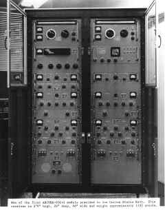
photo from TMC
vintage radio web site |
Each receiver section has:
- 2-32 mc RF input (8 bands)
- 1.75mc first IF
- 250kc 2nd IF
- 1 / 6 / 15 kc symmetric filters
& 3 / 7.5 kc USB & LSB filters
- 2 IF channels feed separate detectors
- 2 detector channels (each with diode detector or product detector)
- 2 AF high & low cutoff filters
- 2 AF line outputs
|
|

|
 |

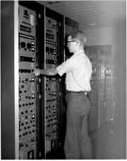
NAVCOMMSTA Guam - 1960's
Download TMC
Data Sheets Here
Download TMC Manuals
Here
|
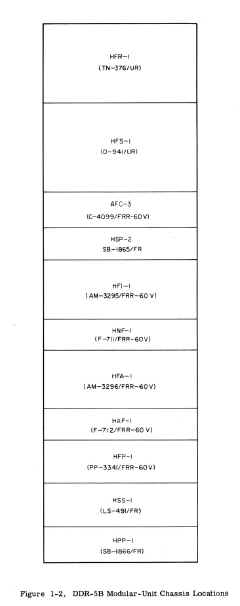
- TN-376/UR (HFR-1) - RF Tuner 2-32 mc
- O-941/UR (HFS-1) - Freq. Synthesizer
- C-4099/FRR-60 (AFC-3) Automatic Freq. Control
- SB-1865/FR (HSP-2) Speaker Control Panel
- AM-3295/FRR-60 (HFI-1) IF strip & filters
- F-711/FRR-60 (HNF-1) IF Notch Filter
- AM-3296/FRR-60 (HFA-1) Detector and Audio
- F-712/FRR-60 (HAF-1) Audio Low/High Pass Filters
- PP-3341/FRR-60 (HFP-1) Power Supply
- LS-491/FR (HSS-1) Speaker
- SB-1866 (HPP-1) Power Panel
|


