Shipboard Transmitter & Receiver Switchboard Interconnections
SHORE STATION TRANSMITTER CONTROL CONSOLE |
|||
AN/FRQ-3 |
Buskin Lake 1955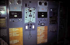 |
Buskin Lake 1955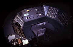 |
|
TRANSMITTER REMOTE CONTROL UNITS |
|||
Transmitter control wiring4-wire and 6-wire control info |
transmitter - radiophone control wiring |
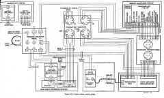 radio system control wiring (rcvr, xmtr, key, audio, remote control, etc.) |
 standard 6-wire transmitter control |
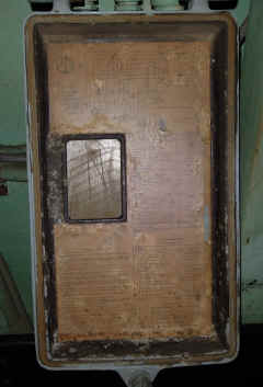
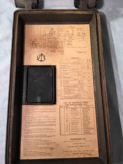
NT-23172 Radiophone unit
|
 |
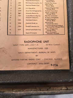
See here for spec sheets | NT-23211 Radiophone unit (6-wire) 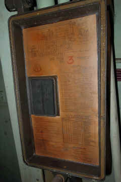 |
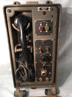
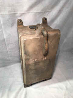
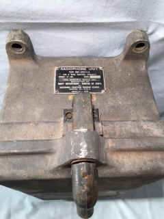
NT-23211 Radiophone Set
|
 |
 |
 |
|
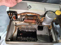
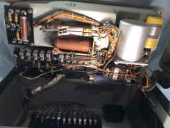
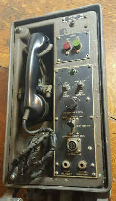
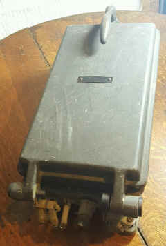
This unit is contained in a housing suitable for bulkhead mounting, and is designed for use in place of Remote Radiophone Unit Navy Type-23500 in outside locations which are open to the weather. Access to the controls is obtained by opening the front cover, which is hinged to the unit. All controls are mounted on the front panel, including a handset. Located on the front panel are the following: MASTER START power on red indicator lamp; START ON-OFF switch controls; CARRIER ON green indicator lamp; ON-OFF KEY ORCUIT switch; NOISE SUPPRESSION NORMAL-ON switch; INCREASE EARPHONE LEVEL control; LOCAL CHEST MIC momentary panel talk switch; LOCAL CHEST MIC extension; LOCAL HEADSET jack; LOCAL CHEST SET jack. |
|||
|
|
 |
 |
 |
|
|
|
 |
 |
NT-23305 remote control unit
|
Manuf - CFN Farnsworth |
||
CNR-23442 transmitter control & keying unit
|
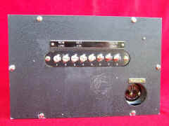
"Remote-Local", "Local Test", "Remote Line", "Key Circuit", "Transmitter Remote" |
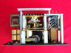
Has 1 tube, several relays, and a time delay switch |
 |
|
|
|
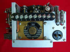 |
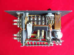
|
Provides for starting and keying transmitter unit over a single pair, or one wire and ground. Transmitter starts when key is momentarily closed and remains on for a delayed time interval after last key impulse is transmitted. Key line resistance 35 DC ohms max; operates from 115/1/60. 9 watts standby, 18 watts operating, keying speed 50 words/minute. For general radio use. |
|||
NT-23445 Remote Channel Selector
|
Remote Channel Selector System (CQC-23445, CQC-23497, CQC-20409) manual The NT-23445 selector unit is contained in a cast aluminum housing which is suitable for bulkhead or top-of-table mounting. A telephone dial, synchro indicator, and an OFF-ON switch are mounted on the front panel. Also mounted on the front panel is a card holder containing a set of cards on which data regarding the ten channels may be marked. A terminal tube is supplied for the cable lead, which is attached at the bottom of the case when the unit is mounted on a bulkhead, and at the back of the case when the unit is mounted on a table top. This unit, when connected into the system for which it was designed, provides remote control for either TDZ or RDZ for selection of any channel in the controlled equipment. Refer to figure 3-30. When the OFF-ON switch, S301, is set to ON, the unit may be operated for control purposes. When the dial is moved in a clockwise direction to the finger stop, the off-normal contacts dose and remain closed until the dial returns to the normal position. When the dial is released, the impulse contacts open and close to pulse an associated loop circuit in the controlled equipment. The resistor network associated with the stepper switch K116 in the TDZ transmitter is energized through various relays, and returns to the M301 indicator the necessary intelligence to operate the receiver selsyn and indicate the channel selected. Setting switch S301 to the OFF position electrically removes this unit from the system. |
||
NT-23496 control panel
|
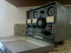 |
Controller for RDZ/TDZ channelized UHF
receiver/transmitter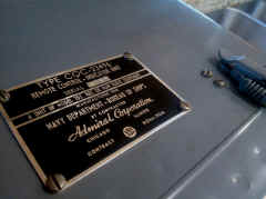 |
manuf CQC Admiral |
|
All of the controls operated at this unit are mounted on the front panel. When the
LOCAL/REMOTE switch, S106, mounted on the front of the TDZ Transmitter is set to REMOTE, the Control Indicator
Unit may be operated. A START-STOP switch, S405, enables the transmitter to be energized or
deenergized from a remote position. A red indicator lamp, I401, indicates when primary voltage is applied to the
transmitter and this control unit. A key jack, J403, is provided on the front panel
for the hand-key plug. Normally, MCW operation may be .accomplished only from a remote position. Two jacks,
J401 and. J402, are employed for connecting a handset to the unit.
RECEIVER switches S401 and S402 connects either the No. 1 RDZ/RDZ-1 or the No.2
RDZ/RDZ-1 to either or both handset jacks. Audio level controls R403 and R404 adjust the audio-level input to each
of the handsets. |
|||
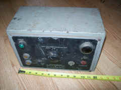
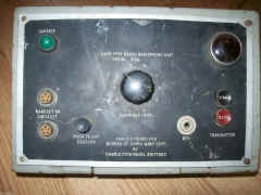
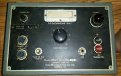
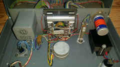
NT-23500 radiophone control unit
|
|
|
Precursor to C-1138/UR
See here for spec sheet
|
|
|
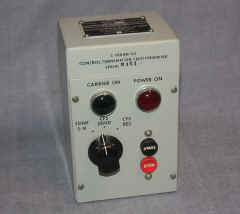
This unit is designed for use with Remote Channel Selector Navy Type -23445. It is installed in sheltered locations. Located on the front panel are the following: TRANSMITTER START-STOP button, POWER ON red indicator lamp, CARRIER ON green indicator lamp, KEY jack, HANDSET or HEADSET jacks, PUSH TO CUT SQUELCH button, and an EARPHONE LEVEL knob. | |
C-1004/SG
|
|
|
|
C-1138/UR
|
Radiotelephone control panel - includes key jack and handset jack | Manual NAVSHIPS 93152 - pdf
Manual pages - |
|
C-1180/GRC-27 radio set control |
need photo | adapts GRC-27 to standard shipboard remote control | NAVSHIPS 92175 |
C-1277/SR Transmitter Control |
Remote power control of 2 UHF transmitters -
co-located with C-1138/UR or similar radiotelephone control box.
The C-1277 allows an operator to energize one or both transmitters (only one at a time if they are on the same frequency). It is suggested that the labels "No.1" and "No.2" be replaced by "FORE" and "AFT" after installation |
C-1277/SR is used with Antenna AS-668/SR and Relay Assembly RE-156/SR. Two of these antennas, each fed by a separate UHF transmitter (such as the TED-9) are mounted shipboard so as to give omni-directional horizontal coverage. |
The C-1277 just has switches and indicator lamps while the RE-156 has the relays that actually control the two transmitters. |
C-3868/SRC
|
|||
|
|
-- | -- | |
C-9044/URC-35 remote control |
Used with AN/URC-35 transceiver |
||
C-10206/URC-94 remote control
|
|
|
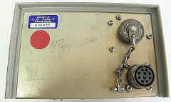
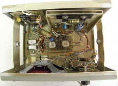
Used with AN/URC-94 transciver |
C-11922/U Remote Control Unit |
What equipment was this used with? | ||
TRANSMITTER AUDIO |
|||
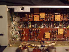
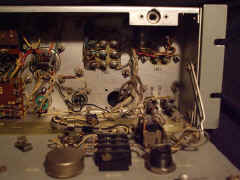
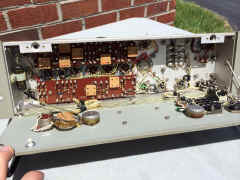
AM-413/G
|
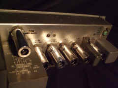
AM-413/G manuf Harmon-Kardon AM-413A/G manuf American Measuring Instruments need more info - Please let me know if you have a manual I can borrow or buy |
||
 |
 |
|
|
|
|
|
-- | ---- |
TRANSMITTER CONTROL PATCH PANELS & SWITCHBOARDS |
|||
|
|
WW2 - 11-line Radiophone patch panel in Radio 2 (Transmitter Room) BB-55 USS North Carolina |
|
|
SB-83/SRT
|
5 transmitters, 10 remotes | These units switch 12-wire control signals -
|
Spec Sheet - thanks to HNSA |
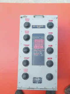
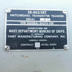
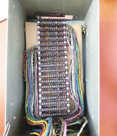
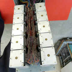
SB-863/SRTtransmitter control switchboard - 19 transmitters, 10 remotes, 12 lines |
SB-863 aboard BB-64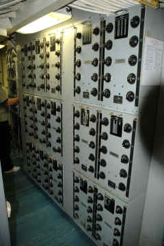 |
SB-863/SRT simplified schematic showing 2 positions of 2 switches |
Dave Cunningham repairing SB-863 on USS New Jersey -
photo thanks to BNJARS
|
|
rear of switches |
switch wafers |
switch wafer removed |
switch wafer socket |
|
 |
 |
|
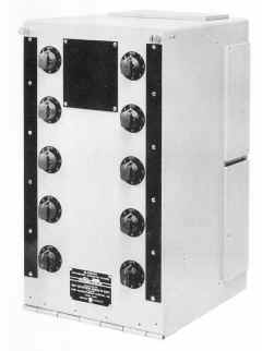
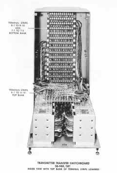
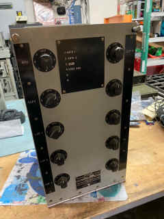
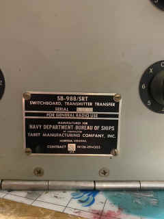
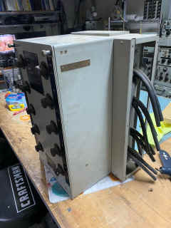
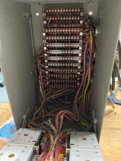
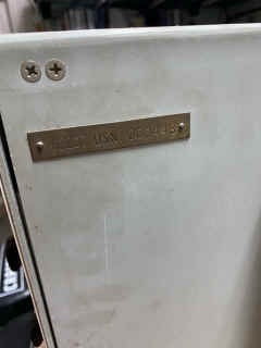
SB-988/SRTtransmitter control switchboard6 transmitters, 10 remotes SB-988/SRT manuf by Tabet |
|
 |
|
|
 |
 |
|
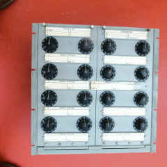
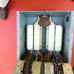
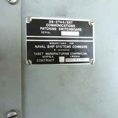
SB-2744/SRT10 transmitters, 16 remotes |
 |
 |
|
SA-770/UR Handset Switchbox |
|
|
|